A warm welcome
… to Crummenerl GmbH — your manufacturer for feather keys and milled parts based on drawings. Certified according to DIN EN ISO 9001:2015 and ISO/TS 22163:2017.
We are specialized in production and distribution of fasteners and precision parts based on technical drawings.
Our core competence is the manufacturing of feather keys according to DIN 6885, as well as various types of keys based on DIN 6888, DIN 28134, DIN 6883, DIN 6887, DIN 6881, DIN 268, and DIN 6886. Our customers value us for our high level of flexibility – we respond to nearly every customer request.
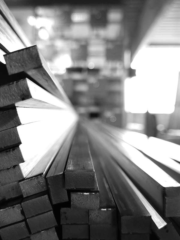
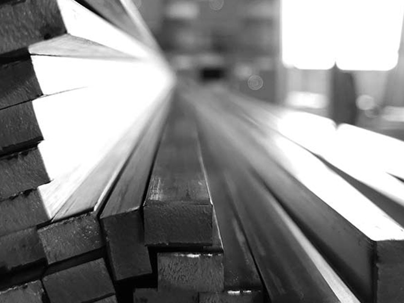
Additionally, we supply key steel according to DIN 6880 – in fixed and production lengths, bright steel with special tolerances, and precision flat steel in ground finish – as cut-to-size blanks with machining allowance or fully machined parts according to customer specifications.
In recent years, we have significantly expanded our CNC production capabilities for complex components with special mechanical properties. For this, we use modern 3-axis and 4-axis CNC milling centers with and/or robots or rotary tables.
Based on many years of experience, we take the time to understand your needs and offer you individual parts according to your requirements.
We look forward to hearing from you!